Material ECA Components | Providing Tremendous Flexibility
In This Article
This article introduces Material ECA Components:
- Why Components
- Types of Components
- Four Ways to Create Components
- Three Ways to Run Components
- They Geometry Type Property
Subsequent articles will describe specific Components and the actions Components can take in more detail.
Why Components
By encapsulating Material ECA functionality as Components, they become interoperable, and Material ECA is a powerful to for fitness-for-service assessments and ECAs (engineering critical assessments) – we can build projects representing real-world, full-lifetime conditions quickly and easily. Specific functionality can do this by sharing certain common properties, such as Geometry Type, and actions, such as Run, Run Batch, and Run Solver. This also makes Material ECA easily extendable. Adding new Components representing additional functionality is straight-forward.
Types of Components
Material ECA uses two types of Components: fracture mechanics and utility components. The fracture mechanics components provide the input data for each specific fracture mechanics calculation, and the utility components facilitate Component interoperability. The Chain and Group utility components allow Components to interact with each other by containing other Components. Innovative fitness-for-service assessments and ECAs are possible since Chain and Group Components can be embedded inside other Chain and Group Components.
Fracture mechanics Components
- Unstable Fracture: BS 7910:2019; Clause 7
- Ductile Tearing: BS 7910:2019, Clause 7.3.8
- Fatigue Crack Growth: BS 7910:2019, Clause 8
- Unstable Fracture: API (American Petroleum Institute) 579 (coming next)
Utility Components
- Chain: Components contained in a Chain Component will be assessed in series, with the initial flaw for one contained Component being the final flaw for the previous contained Component. The final flaw for the Chain will be the final flaw for the final contained Component in the Chain. If any contained Component is unacceptable, the Chain will be unacceptable.
- Group: Components contained in a Group will be assessed in parallel, with the initial flaw for all contained Components being the initial flaw for the Group. The final flaw for the Group will be the largest of each of the Components contained. If any contained Component is unacceptable, the Group will be unacceptable.
- Max Flaw Size: a list of flaw sizes (flaw height and length) representing a line on a flaw height vs. flaw length chart is input to the Max Flaw Size Component. If the initial flaw is larger than the Max Flaw Size line or grows larger than the line, the Max Flaw Size Component will be unacceptable.
Plans to expand the capabilities of Material ECA include adding analogous fracture mechanics components for API 579.
Four Ways to Create New Material ECA Components
Material ECA components can be created in the following ways:
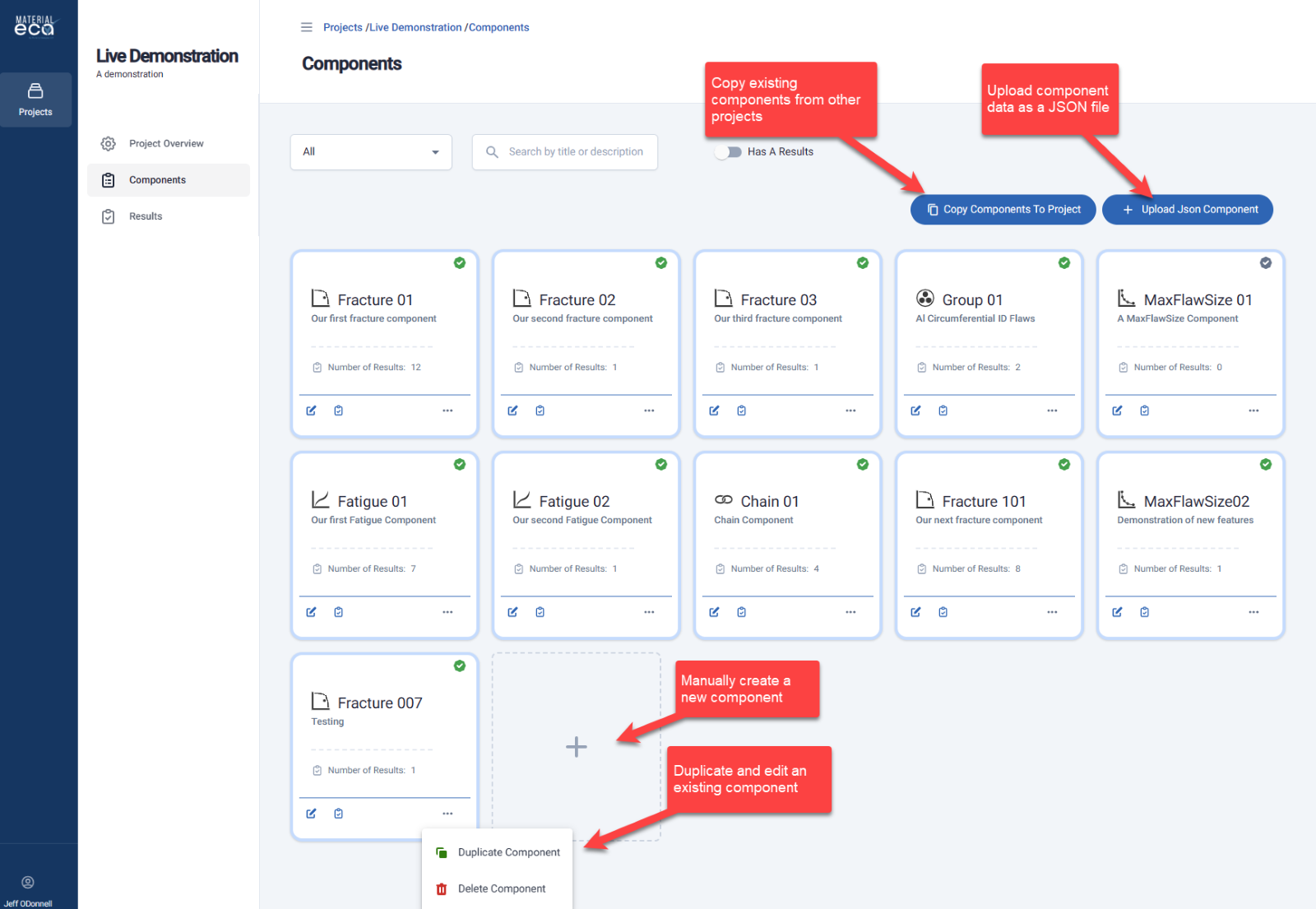
Manually completing a Create Component form opened from the Components page is the most straightforward and detailed.
Duplicating and editing an existing component from the Components page allows users to create several similar components rapidly.
Copying an existing component from another Project allows users to move data between projects.
Uploading data for a new component from a JSON file allows users to create Material ECA data programmatically outside of Material ECA and save it as a JSON file. JSON is a common, standard format for moving data between platforms.
Material ECA Components can be exported as JSON files, allowing users to develop their own Component libraries and share Components with other users to expedite future fitness-for-service assessments and ECAs and facilitate knowledge transfer.
Three Ways to Run Components: Run, Run Batch, and Run Solver
Running An Initial Flaw
When a Component is Run, the User inputs the dimensions of an initial crack-like flaw, and the acceptability of the initial flaw, the dimensions of the final flaw, and the detailed results are returned.

Running Multiple Initial Flaws
A Component can run as a Batch, such that the User inputs the dimensions of multiple initial crack-like flaws, and the dimensions of the final flaws and their acceptability are returned.
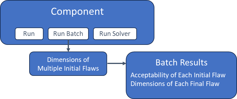
Running the Critical Initial Flaw Solver
A Component can run the Solver, where the User inputs some options, and an array of the critical initial crack-like flaws is returned.

The Geometry Type Property
The Geometry Type is the most significant property common to all Components. Available Geometry Types are:
Plate Geometry Type

The Plate geometry type assesses surface and embedded flaws in rectangular sections. It uses the solutions of BS 7910:2019 M.4.1, M.4.5, P.5.1, and P.5.3.
Plate Corner Geometry Type

The Plate Corner geometry type assesses corner flaws in rectangular sections. It uses the solutions of BS 7910:2019 M.5.1 and P.6.1.
Circumferential OD Geometry Type

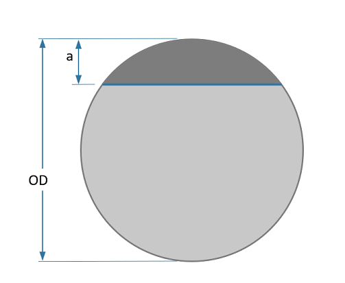
The Circumferential OD geometry type assesses circumferentially aligned OD surface and near-OD embedded flaws in cylinders and pipes. It uses the solutions of BS 7910:2019 M.6, M.7.3.4, M.4.5, P.9.4, and P.5.3.
Circumferential ID Geometry Type

The Circumferential ID geometry type assesses circumferentially aligned ID surface and near-ID embedded flaws in cylinders and pipes. It uses the solutions of BS 7910:2019 M.6, M.7.3.2, M.4.5, P.9.2, and P.5.3.
Axial OD Geometry Type
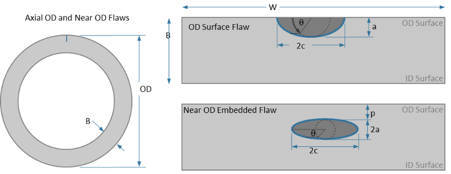
The Axial OD geometry type assesses axially aligned OD surface and near-OD embedded flaws in cylinders and pipes. It uses the solutions of BS 7910:2019 M.6, M.7.2.4, M.4.5, P.8.4, and P.5.3.
Axial ID Geometry Type

The Axial ID geometry type assesses axially aligned ID surface and near-ID embedded flaws in cylinders and pipes. It uses the solutions of BS 7910:2019 M.6, M.7.2.2, M.4.5, P.8.2, and P.5.3.
Round Straight Geometry Type
The Round Straight geometry type assesses straight surface flaws in solid round sections. It uses the solutions of BS 7910:2019 M.10.1 and P.12.1.
The Next Article is The BS 7910 Fracture Component | A Deep Dive
Last Updated 29 May 2024