The BS 7910 Tearing Component | Deep Dive

In This Article
The BS 7910 Tearing component automates the methods described in BS 7910:2019 for stable ductile crack growth under static loading. As such, this procedure is specifically applicable to steels displaying upper-shelf toughness behavior, austenitic alloys, etc. The Tearing component does not inherently address unstable tearing or fracture, and it does not address the impact of biaxial loading. This article provides a detailed description about how to use the component, how the component works, its options, and settings. It is assumed the reader is familiar with the Material ECA BS 7910 Fracture component; if not, please read the article for that component before reading this one. The user is expected to be familiar with BS 7910 and should reference their own copy of the document, as appropriate. The topics are covered in this article include the following:
- Overview
- Creating a New Tearing Component
- Geometry Input and Options
- Stress Input and Options
- Material Tensile Input and Options
- Tearing Resistance (J-R) Curve Input and Options
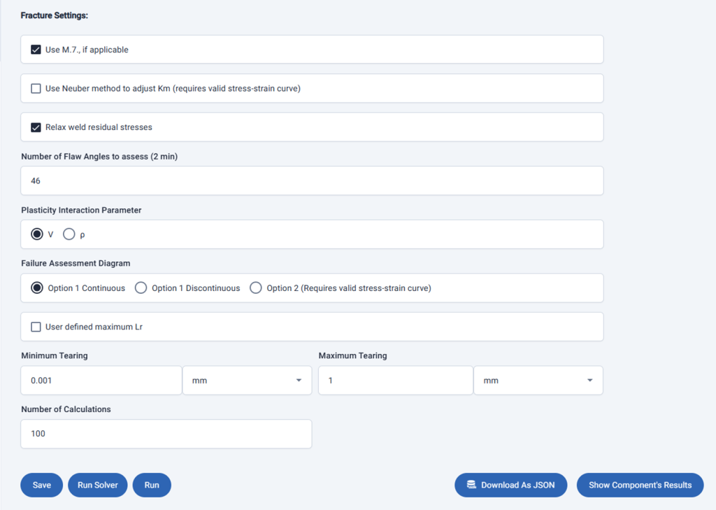
- Tearing Settings
- Running a Tearing Component and Viewing the Results
Overview
The BS 7910 Tearing component assesses the stable growth and acceptability of an initial crack-like flaw consistent with the methods described in BS 7910:2019 Clause 7.3.8 based on stress intensity solutions described in Annex M, and the reference stress solutions described in Annex P. The Tearing component takes a tearing-resistance (J-R) curve as input. As shown in this next chart, the toughness, in terms of the crack driving force or J, depends on incremental crack growth (Da). When incremental crack growth is a low value, the tearing resistance is low, regardless of the initial flaw size.
The Tearing component takes the following input settings (default values provided):
- Minimum Tearing (0.001mm)
- Maximum Tearing (1.0mm)
- Number of Calculations (100)
When run, the Tearing component calls the Fracture component up to the Number of Calculations to return an array of Kr and Lr values using incrementally larger incremental crack growth values (Da), which incrementally increases the flaw height, flaw length, and toughness, until stable tearing arrests. If stable tearing does not arrest before Maximum Tearing is reached the flaw is Not Acceptable.
The following two charts illustrate Tearing results for Acceptable and Not Acceptable initial flaws. For ductile tearing assessments, the area of the failure assessment diagram (FAD) above the failure assessment line is associated with stable tearing, and the area below the failure assessment line is associated with no stable tearing. The initial assessment points typically have Kr values substantially larger than 1.0, so stable tearing is present. As incremental crack growth increases, the Kr values decrease because tearing-resistance (toughness) increases faster than the crack driving force increases. If the assessment points go below the failure assessment line, the calculations end, and the initial flaw is considered Acceptable. Otherwise, the calculations end when the maximum tearing is reached, and the initial flaw is considered Not Acceptable.
Because the Tearing component does not address the potential for unstable fracture, it is recommended to use a tearing component inside a Chain component before an appropriate Fracture component. This way ductile tearing and unstable fracture can both be addressed.
The most common way Tearing components are used for Offshore and Subsea applications is to address ductile tearing during Reeling installation operations consistent with the procedures described in DNV RP-F108. Depending on the installation, 2-6 Tearing components are created each to represent a cycle, they are then placed inside a Chain component, which represents the entire reeling installation event.
Creating a New Tearing Component
A Tearing component is created the same way a Fracture component is created. From the Components page, click the tile with the plus (+) sign. In the Add New Component form, select “Tearing”, “BS 7910:2019”, add a name and description, and click Save, as shown in here.
The newly created Tearing component is available on the Components page. Click it to open it.
Geometry Input and Options
Geometry input and options are like those for the Fracture component, as shown in the following figure. Let’s provide input like what was done for the Fracture component article.
Loading Input and Options
Loading input and options are like those for the Fracture component, as shown in the following figure. Let’s provide input as shown here:
Material Tensile Input and Options
Material Tensile input and options are like those for the Fracture component, as shown in the following figure. Let’s provide input like what was done for the Fracture component article.
Tearing Resistance Input and Options
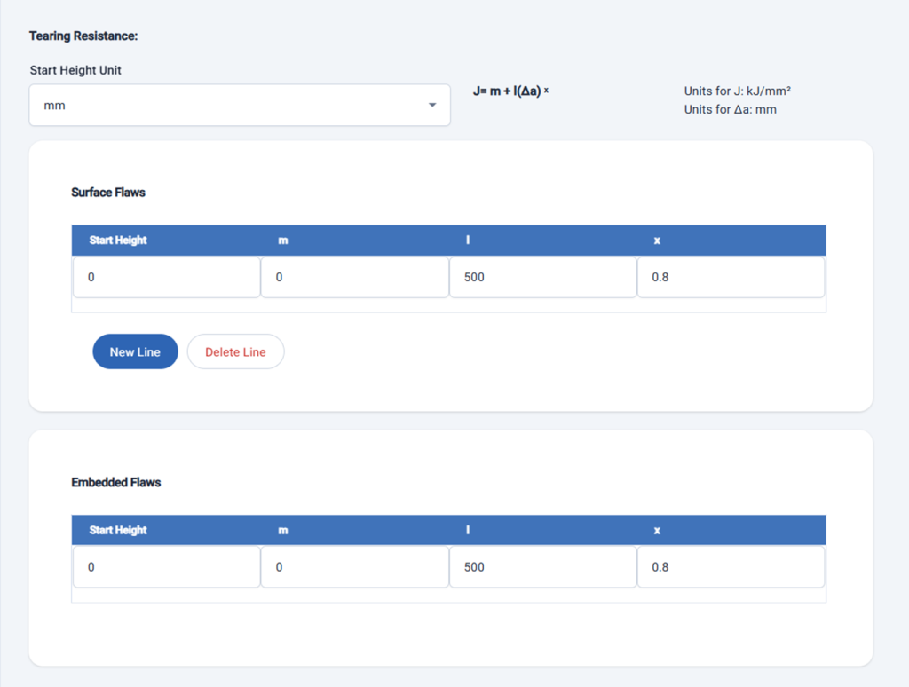
Tearing resistance (J-R) curves must be input for both surface and embedded flaws, as shown here:
The Start Height value and unit inputs are only needed for assessments involving non-homogeneous fatigue crack growth and can be ignored otherwise.
Tearing resistance curves are modelled as a biased Power-law having the following form:
J = m + l (Da)m
Values for m, l, and m are required.
Tearing Settings
The Tearing Settings include all those used for the Fracture component. The ones specifically for ductile tearing calculations are Minimum Tearing, Maximum Tearing, and Number of Calculations, which are described earlier in this article.
The value for Minimum Tearing must be a number larger than 0. The default value is 0.001mm.
The value for Maximum Tearing is recommended to be no more than 1 to 2 mm. The default value is 1.0mm.
The value for Number of Calculations will govern the resolution of the result. The more calculations, the more accurate the result will be. The default value is 100, which is associated with a default resolution of 0.01 mm.
Running a Tearing Component and Viewing the Results
Click the Run button, and the Input Initial Flaw form appears. Input the desired initial flaw, as shown, and click the Run button.
Navigate to the Results page for the component and click anywhere on the row associated with the current result to view it. The top of the Results view shows whether the run was completed successfully and if the final flaw was acceptable. The initial and final flaw sizes are provided next.
The flaw growth chart is dynamic; the user can hover the cursor over the curve to see the coordinates for every point. Below the chart are additional details, like those provided in results for Fracture components. Next are the buttons, which are like those for the results for the Fracture component.
Like results for the Fracture Component, the Tearing results can be exported as Excel or JSON. A Report suitable for documenting the run provides all input and summarizes the results; it can be exported as a PDF file.
Next Article: Group Component
Last modified: 07 July 2024


