Engineering Critical Assessments (ECAs) for Managers

ECAs have progressed from reactive, fitness-for-service tools to proactive methods for design, qualification, and life extension for modern energy and offshore industry projects. By understanding the mechanical limits of materials and quantifying the acceptability of crack-like flaws, contemporary ECAs provide a vital technical foundation to establish technically-sound flaw acceptance criteria, optimize safety and reliability, and eliminate redundant fabrication repairs.
For project managers, capitalizing on the value of an ECA relies on clear project interfaces, proactive engineering oversight, and integrated data. Establishing a rigorous methodology document early on, planning for material testing schedules, and engaging technical expert reviews are steps to ensure project execution remains smooth, cost-effective, and safe.
Introduction
Engineering critical assessments (ECAs) are fracture mechanics-based assessments that help determine whether engineering systems, such as pipelines, vessels, piping systems, or structures, can withstand specific events and conditions without failing or losing containment. They do this by assessing the acceptability of crack-like flaws related to the potential for unstable fracture, fatigue crack growth, ductile tearing, and other mechanisms.
A ‘flaw’ it in context of ECAs is usually a weld imperfection, such as lack of fusion or lack of penetration. Although a flaw can exist in the parent material, welds are inherently more susceptible due to a number of factors, and they are typically the focus of ECAs in the offshore industry.
ECAs can provide meaningful input to:
- Assessments of new materials, designs concepts, and processes
- Selection of welding procedures and non-destructive examination (NDE) system requirements
- Providing acceptance criteria for flaws
- Fitness-for-service of items with detected flaws or having experienced unanticipated scenarios
- Assessments for life extension and repurposing
ECAs can help projects and organizations make smarter decisions and improve safety by:
- Establishing the acceptability of flaws now and in the future
- Characterizing a component’s tolerance or sensitivity to material or fabrication flaws and imperfections
- Providing technical basis for cost-effective NDE, repair, and life-extension plans
- Eliminating unnecessary repairs
ECAs consider the following factors:
- Size, location, and orientation of flaws and imperfections
- The detailed geometry of the item and weldment containing flaws
- Stresses and cyclic stresses acting on the region containing flaws
- Toughness, tensile, and fatigue properties of the material in the region containing flaws
Industry Standards
The two common standards that generically describe methods for conducting ECAs are API 579 and BS 7910.
Standards that describe the implementation of ECAs for pipeline systems include API Std 1104, CSA Z662, API Std 2RD, and DNV RP-F108.
Standards that describe the implementation of ECAs for offshore structural systems include API RP 2A-WSD, ABS Guide on Fracture Analysis for Marine and Offshore Structures, ISO 19902, and DNV RP-C203.
ECA Concepts and Applications
The classic concept of an ECA assesses the acceptability of a crack-like flaw and as illustrated in Figure 1, is dependent on input in three functions: 1) loading, such as stresses and cyclic stresses, 2) material properties, such as strength and toughness, and 3) non-destructive examination (NDE), such as flaw sizes, positions, and orientations. This concept was developed for fitness-for-service assessments, which is assessing the acceptability of a flaw detected during NDE. Industry standards BS 7910 and API 579 explicitly describe the classic ECA.
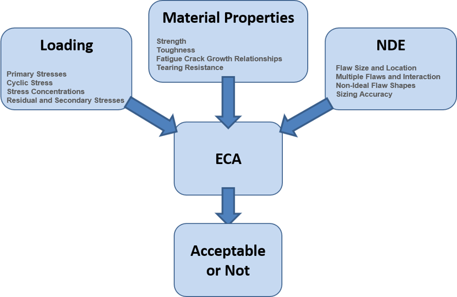
Figure 1: A classic ECA is dependent on three functions: loading, material properties, and NDE and is ideally suited for fitness-for-service assessments
A failure assessment diagram (FAD) is used to assess the acceptability of a flaw considering the flaw may grow over time and become not acceptable, even though it may be acceptable in its initial condition. The FAD is a chart of fracture ratio (Kr) and load ratio (Lr). The failure assessment line separates regions where flaws are acceptable (below) and not acceptable (above). Flaws are assessed by determining Kr and Lr values at various time points during the remaining lifetime. The flaw is assessed to be acceptable if all points, from initial to end-of-life, are below the failure assessment line. Figure 2 illustrates an assessment of an acceptable flaw.
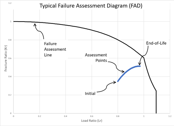
Figure 2: A typical failure assessment diagram (FAD) assessing the acceptability of a flaw including its growth from initial to end-of-life.
Contemporary ECAs
ECAs have evolved to expand their scope from fitness-for-service assessments to supporting the design and development of offshore and subsea systems to meet the challenging demands of deeper water and increasingly onerous conditions. For example, it is reasonable to question whether the empirical, workmanship weld flaw acceptance criteria of API Std 1104 are appropriate for deepwater risers and pipelines. These systems may be subject to substantially greater dynamic loads and fatigue cycles, calling applicability into question. An ECA done during design can confirm what flaw sizes must be reliably detected and addressed during construction, so appropriate NDE system requirements can be specified and implemented. Appendix A of API Std 1104 describes such methods.
Furthermore, an ECA can contribute in meaningful ways in development of new materials, designs, and methods. For example, as part of the process of developing a new high strength steel, allowable stress and cyclic stresses will be higher. The implications of this may include material toughness should be higher, flaw acceptance criteria should be tightened, or some balanced combination of the two should be considered to maintain analogous levels of reliability; an ECA is an ideal tool for such an assessment.
The contemporary ECA approach is like the classic ECA; however, it inverts the dependency on NDE. In other words, NDE depends on the results from an ECA, rather than an ECA depends on the results of NDE, as illustrated in Figure 3.
Figure 3: The contemporary ECA inverts the dependency of the NDE function, which expands its scope of application beyond fitness-for-service assessments
The results of a contemporary ECA are the critical initial flaws, which are the smallest flaws that may become “not acceptable” and must be detected and addressed. They are plotted on a chart of flaw height, which is the size in the through-wall thickness direction, vs. flaw length, which is the dimension parallel to the surface. For design ECAs, these are used to develop NDE system requirements. Figure 4 illustrates typical initial critical flaw solver results. In this case, the solver assessed more than 4000 points, where each individual point represents an assessment like the one shown in Figure 2. Each point addresses all flaw growth between welding and end-of-life, including transportation, storage, installation, commissioning, and operation. Points colored green are those that are acceptable, and those colored red are not acceptable. The points at the intersection between the two are the critical initial flaws.
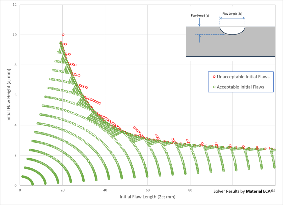
Figure 4: Raw critical initial flaw size solver results identify the smallest flaws that may become critical by the end-of-life. Each point addresses all potential flaw growth scenarios, like a classic ECA.
Additional critical initial flaw curves are produced for different flaw locations within a weld, different weld locations along the riser or pipeline, and different scenarios or events that need to be considered. When processed together and NDE system flaw sizing tolerance is considered, a critical initial flaw chart is produced like the one shown in Figure 5. Historically, flaw acceptance criteria were presented like the “stair-step” shown; however, industry is increasingly using a curve instead.
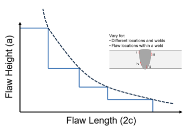
Figure 5: Typical flaw acceptance criteria generated using critical initial flaw size results, considering all possible scenarios and events, and NDE system sizing tolerances.
It’s important to be aware when NDE indications are being assessed during construction that the ECA calculations are based on ideally shaped flaws, i.e., they are shaped like an ellipse or semi-ellipse, and actual weld flaws are far more variable in shape and behave differently. Furthermore, when multiple small flaws are sufficiently close together, they can interact and also behave differently. BS 7910 and API 579 provide guidance on methods for handling such conditions.
ECAs of deepwater riser and pipeline systems done during the design phase usually use specified minimum and maximum material properties, whichever is limiting. When material and weld properties become available later during the construction phase, the ECA may be updated using values that are better representative of the actual materials.
Considerations for Managers of ECAs
The delivery of a successful ECA is contingent on good communication, from communicating expectations to making sure data and information needed for the ECA is provided. The manager may request that the ECA practitioner drafts a methodology document reflecting the ECA practitioner’s best understanding of the requirements and expectations and how they will be implemented as part of the ECA. The methodology document should include the following:
- The extent to which the ECA practitioner will be responsible for or otherwise involved with stress analyses, material testing, and NDE
- What data is needed and how will it be collected and processed
- Use of safety factors
- How input values that are not explicitly known will be handled and agreed
- How the calculations will be done and what software will be used, if any
- Proposed timeline for progress updates
- How the results will be reported and verified
Because the ECA is dependent on data and other information usually produced by others, the person responsible for the ECA needs to take ownership of the data by vetting it as best possible. The manager may ask how they plan to do that and how the manager can help facilitate the process.
A manager may choose to use an independent expert to review and check the ECA providing valuable confirmation of the results. In addition, when a reviewer with substantial experience is on board earlier in the process, issues that can stress the schedule can are better able to get addressed smoothly.
A manager may want to be prepared in advance with information about the extent of material testing needed and have a reasonable estimate of how long the testing will take. These tests can be time-consuming and take a significant portion of the schedule dedicated to the ECA, especially if fracture and fatigue crack growth rate testing in a particular environment, such as those involving H2S, H2, or CO2 will be undertaken.
Acknowledgements
The author would like to express his gratitude to Michael D. O’Donnell (Lead Installation Analysis Engineer, Technip FMC) and Bin Li (Principal Riser Engineer, Genesis Energies) for their valuable suggestions and insightful editorial comments, which significantly improved the clarity and quality of this article.